
Electromechanical Design: Motor Control
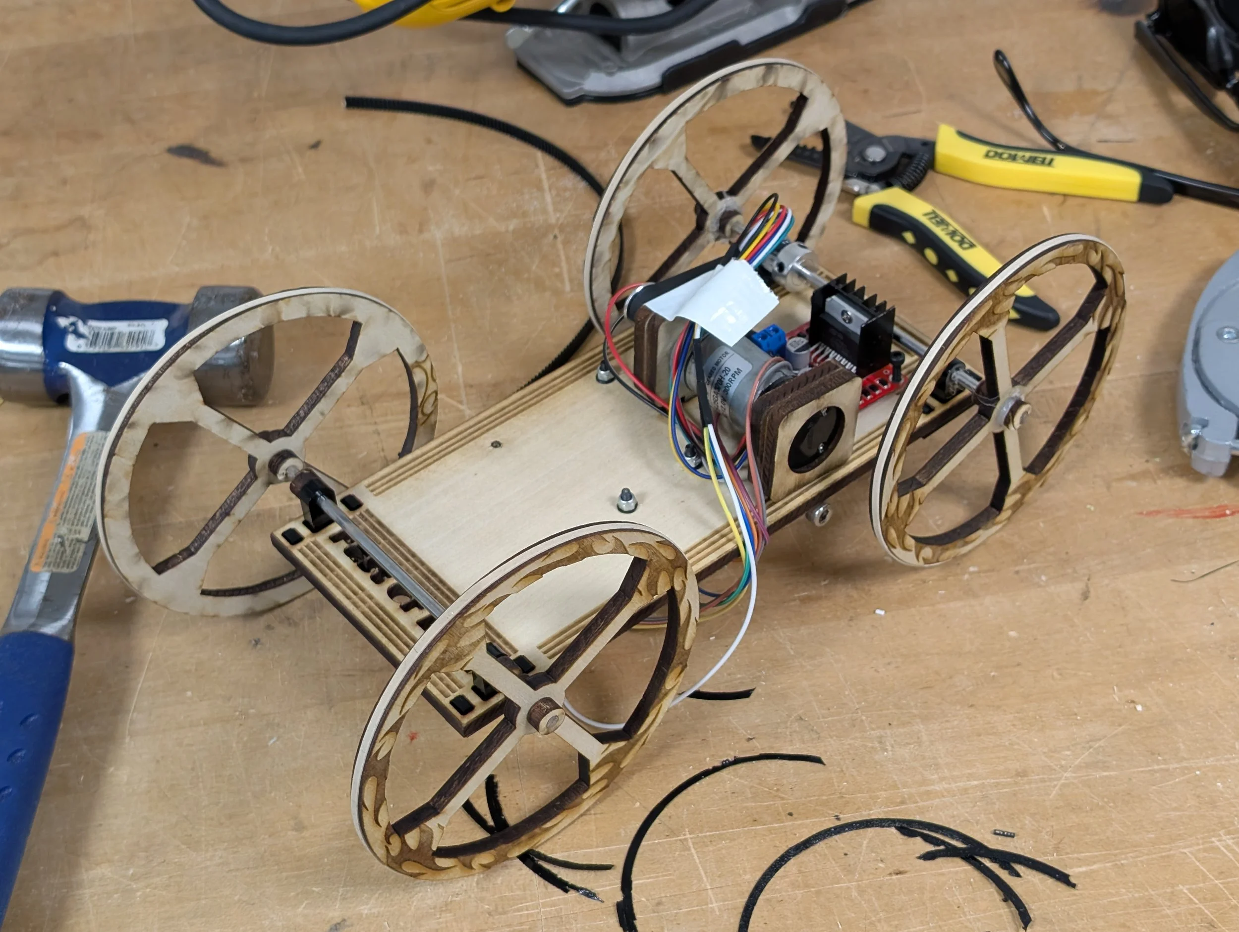
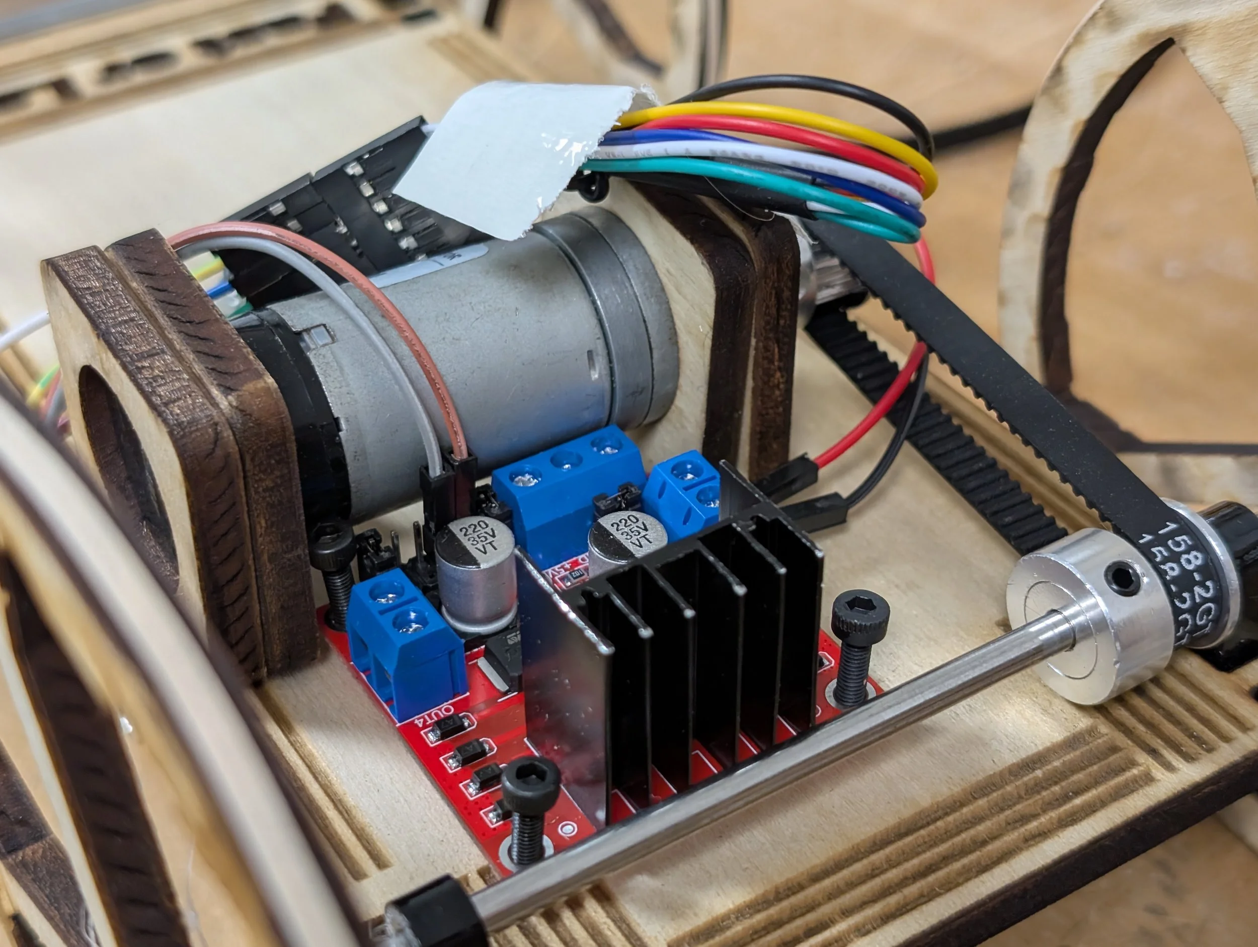
For this project, we were tasked with moving an upright beam between 2 points as quickly as possible. We were provided a 12V motor with encoder, an Arduino and the vehicle’s axle and belt. The rest was up to our team.
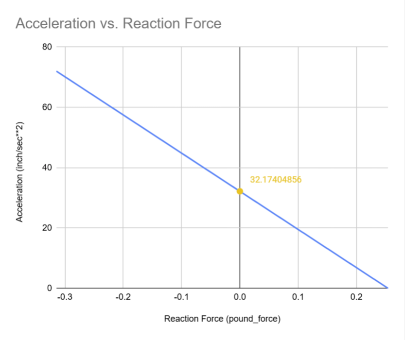
Calculations & Simulation
The max acceleration was calculated by measuring the reaction force on the front edge of the beam as a linear acceleration was applied
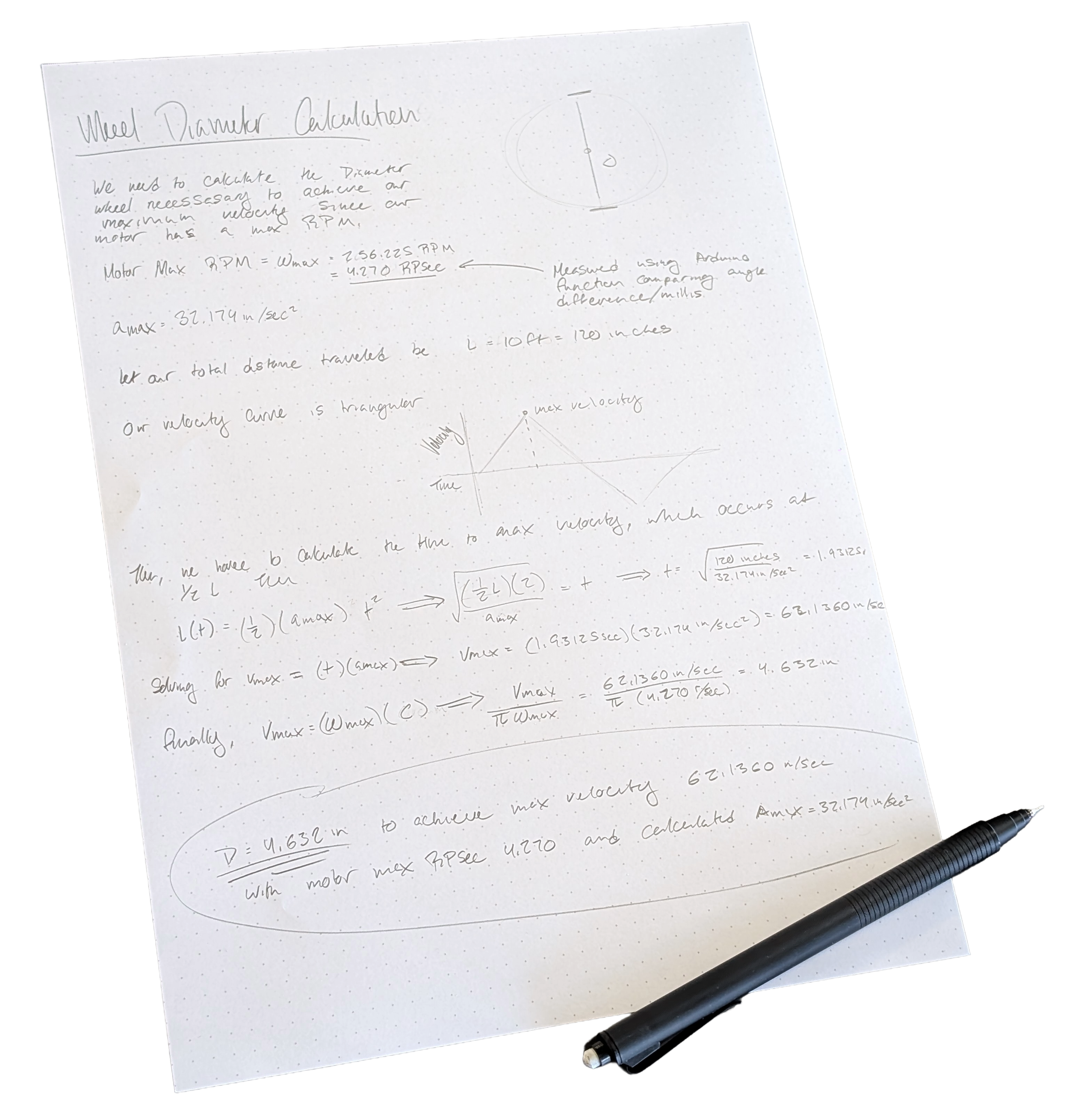
By measuring the motor’s max RPM, we were then able to solve for the ideal wheel size of 4.631 Inches
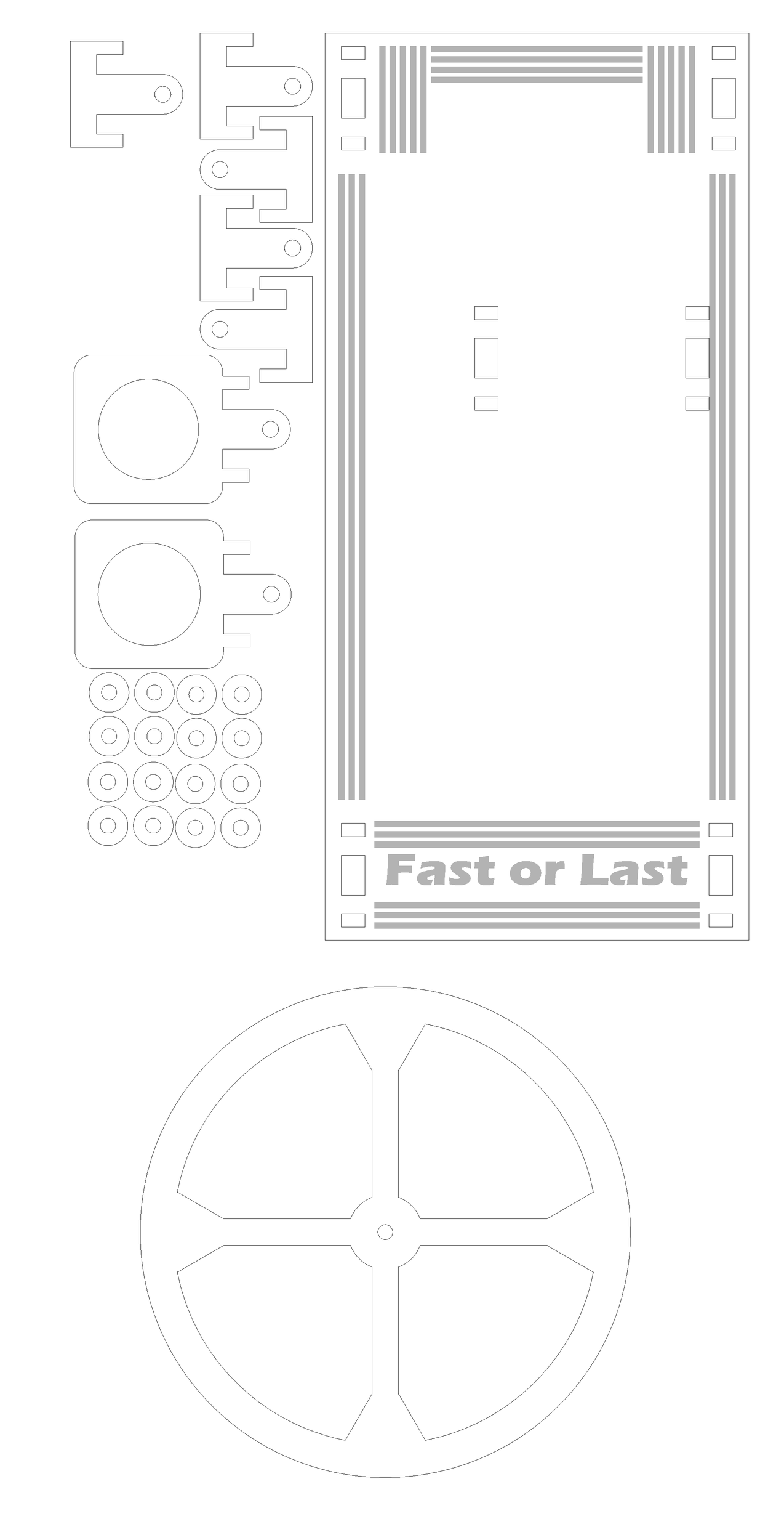
Design
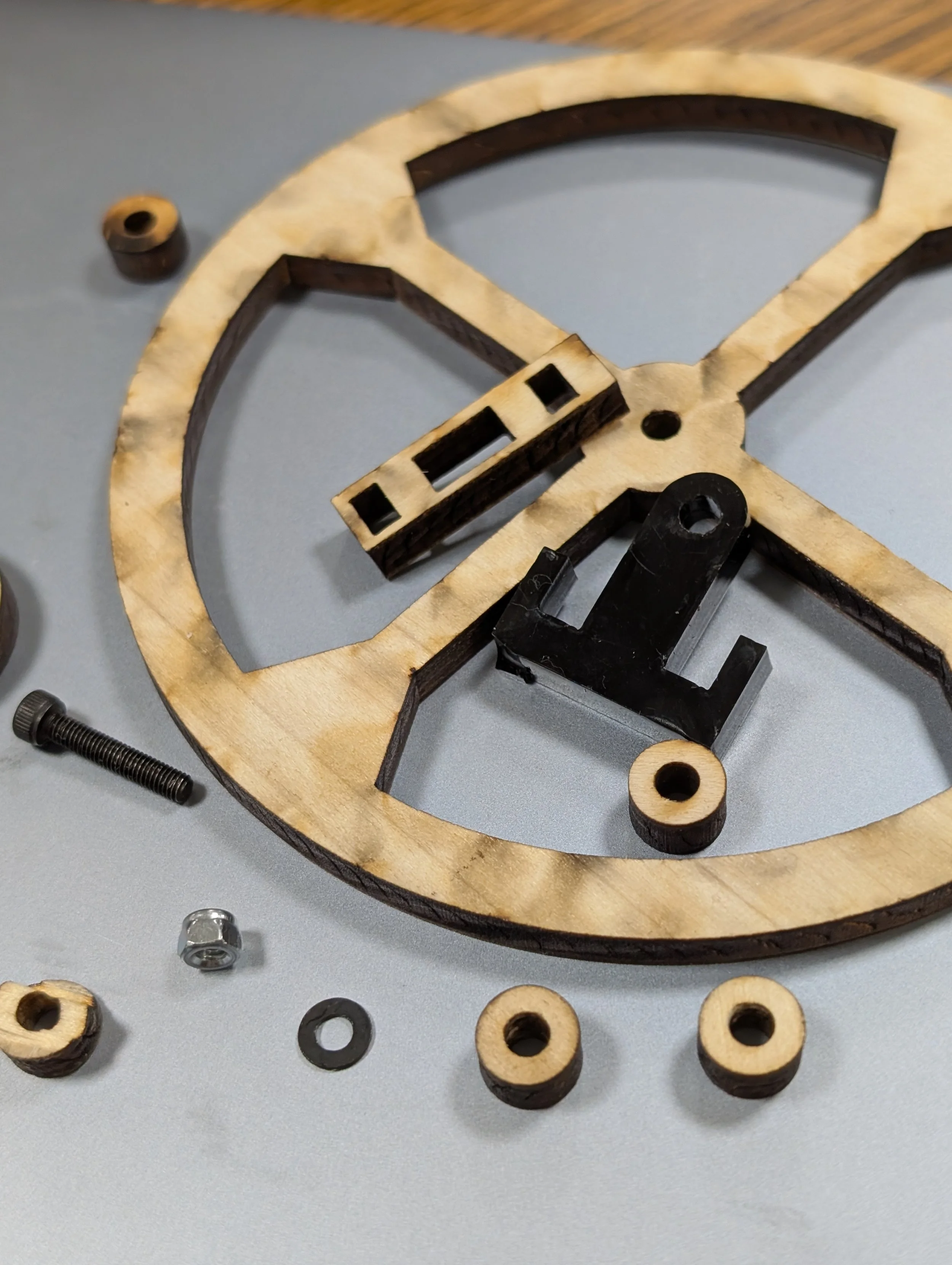
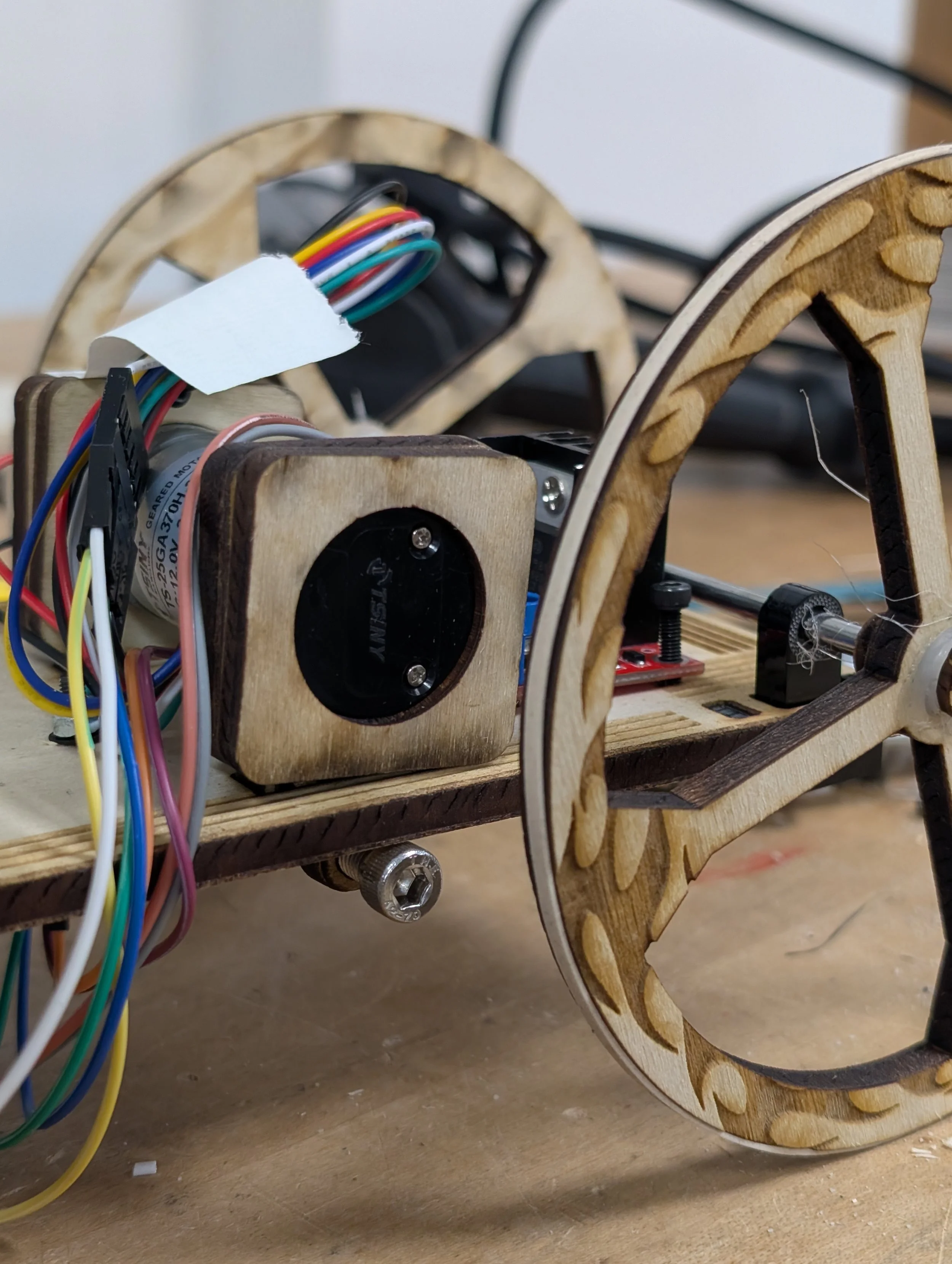
Employing the laser cutter instead of the 3d printer allowed the team to iterate faster, dialing in press-fit tolerances in minutes instead of hours
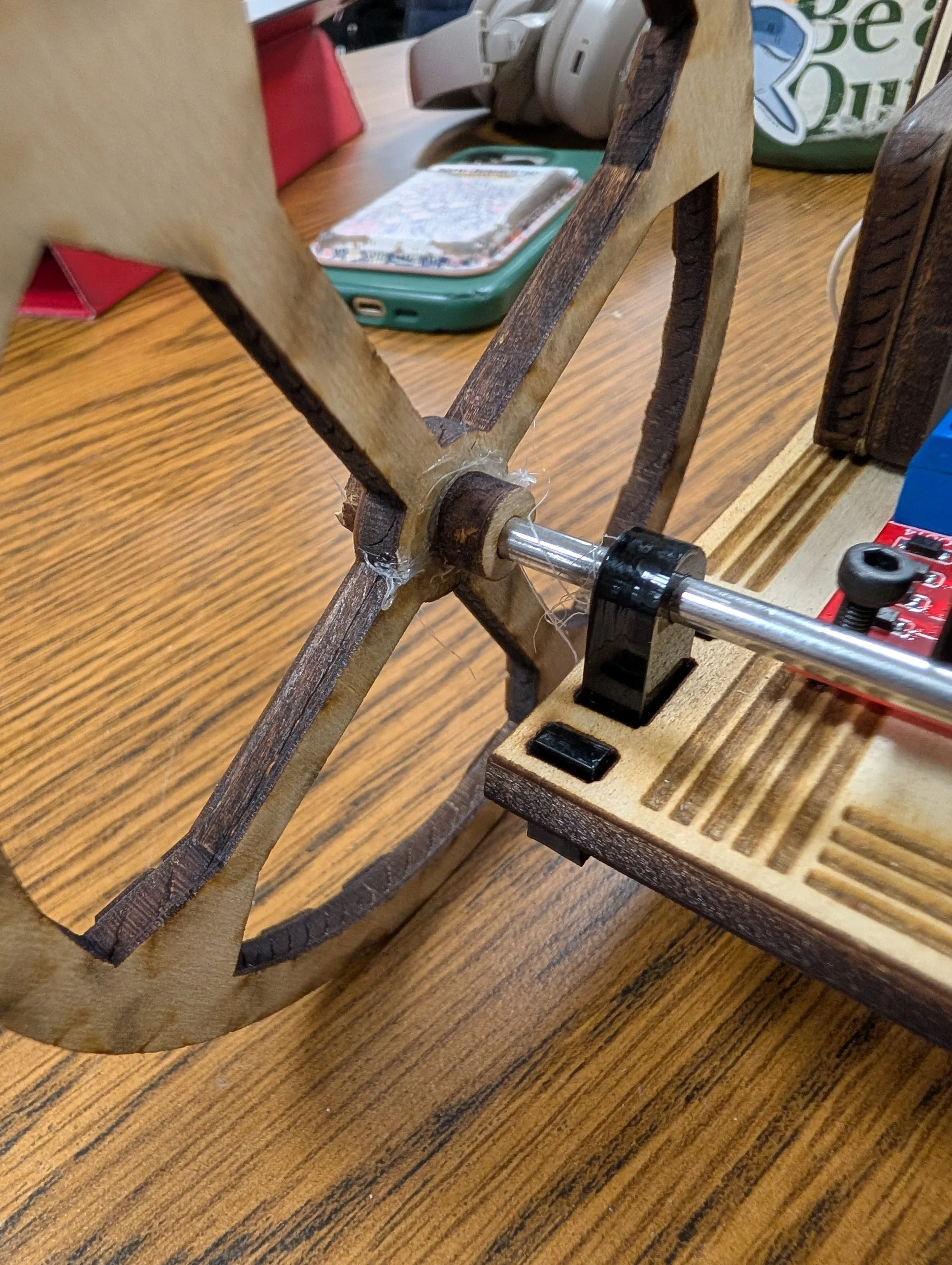
The wheel diameter was reduced to 4.61” to allow for rubber bands providing much needed traction
Hot glue was reluctantly employed at the axles. Even a tight press fit did not supply the necessary friction
Code
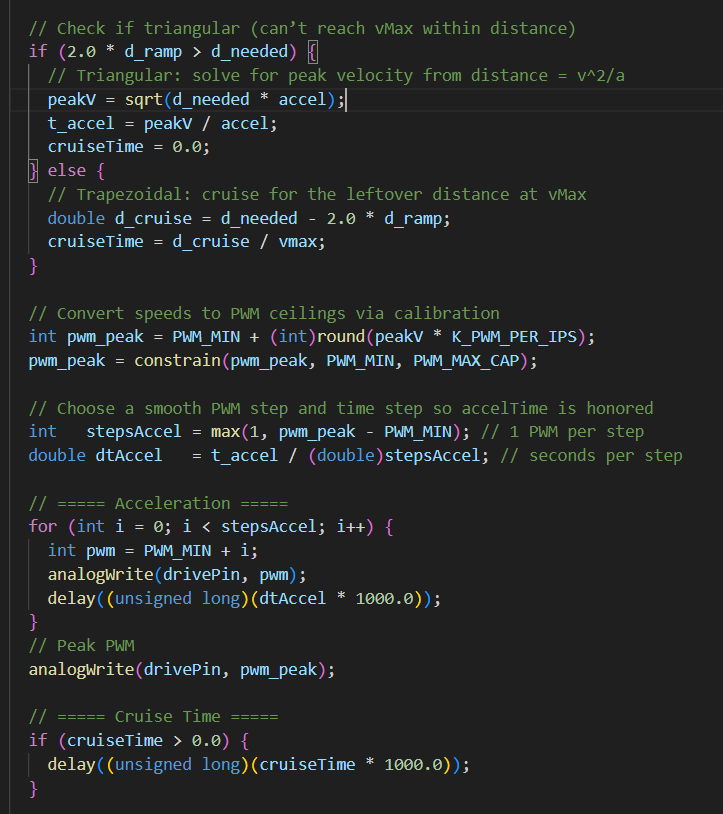
This snippet of code handles the velocity profile follower ensuring the maximum acceleration is never exceeded. It also handles the case where max acceleration is not reached and velocity is kept constant
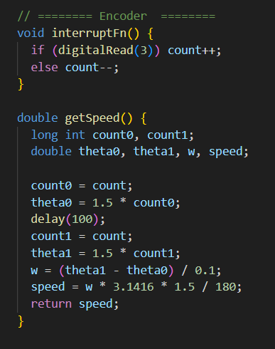
This utility function measures the change in angle over a short period of time, allowing us to measure the maximum RPM, crucial in determining the wheels maximum diameter
Presentation and Reflection
During the day of presentation, our car struggled to make the 10ft distance, but after some quick changes we were able to successfully transport the beam
I primarily handled project management and design and am proud of the outcome. For similar future projects, I would lay out smaller deliverables and delegate the design work to expand my breadth and increase team buy-in